The Pool Diaries
I have a friend with a pool. This friend—let’s call him Tom for anonymity—built this pool himself. It sits in a massive garden next to a pond that was created at the same time. Between the pond and the pool, Tom built a wooden deck with a parasol and loungers, perfect for spending long afternoons.
Tom also has a wife and children who use the pool. His family loves the pool and uses it often. But after a year of operation, one specific complaint grew louder and louder: the pool was too cold. Outside of midsummer—during the first and last warm days of the year—the water temperature was simply too low for his family’s liking.
Tom takes complaints seriously. Although he didn’t quite share the sentiment (he felt 15°C was perfectly fine for a pool), he decided to address it. Any sane person would have marched to the nearest hardware store, bought a heat pump-based pool heater, and installed it. The family would have been happy, and all would have been well.
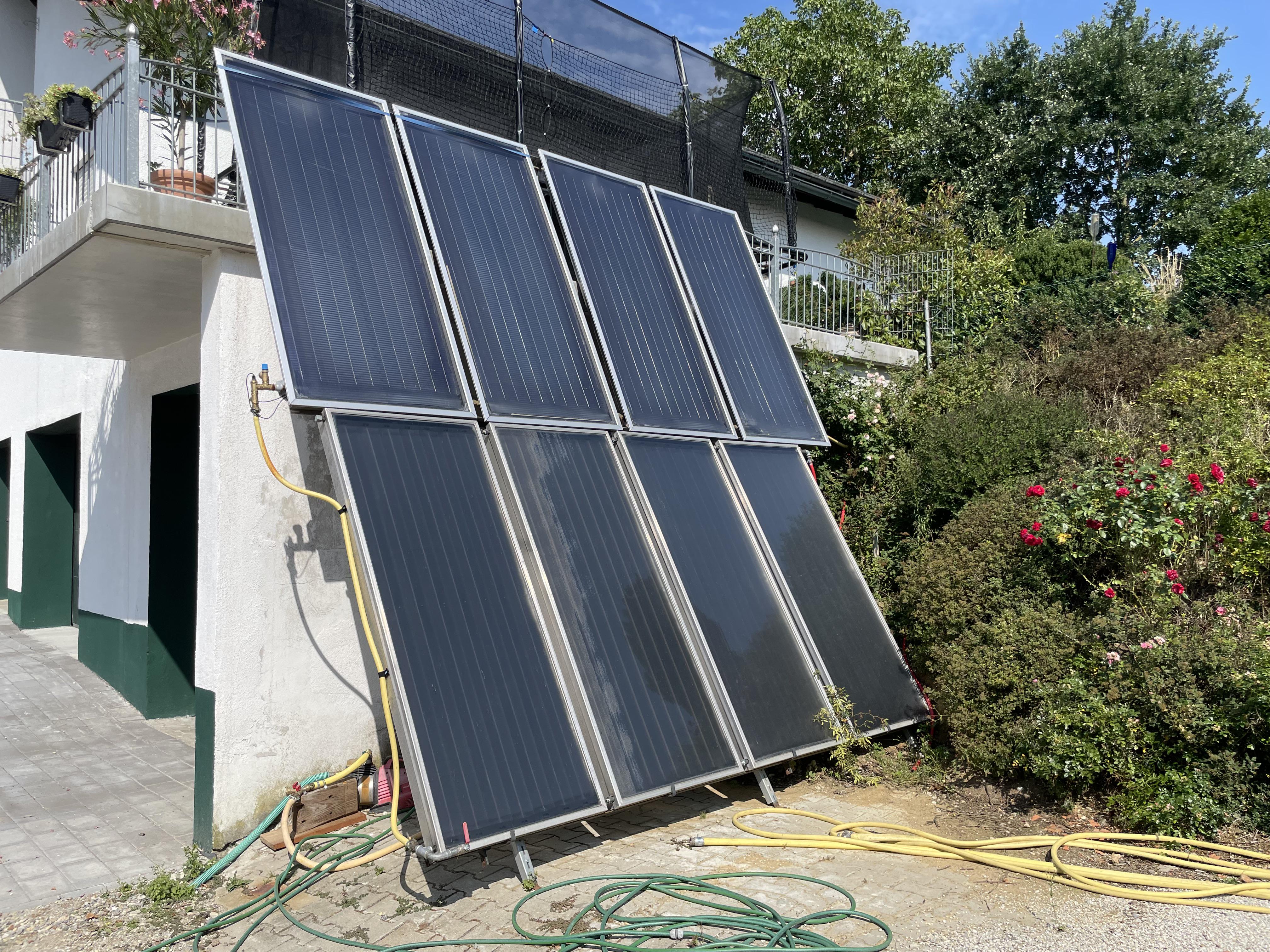
Not Tom. The garden is part of a former farm, so there’s plenty of space. Also, Tom loves welding. What could be more obvious than buying used solar thermal panels, mounting them on a custom-welded steel frame on the garage facade, and extending the filter circuit to include these panels? The result was about 10kW of heating power in his filter circuit.
At first, it worked well; the pool warmed up noticeably faster on sunny days, and the family was satisfied. But soon, the need for even more “pool days”—and thus higher heating power—arose. Tom set out again to get more panels and expanded the system to a staggering 20kW. The pool was now warm—at least as long as the pump was running. However, if someone forgot to turn on the pump, the pool stayed cold. Worse still: if the water in the panels didn’t circulate during sunshine, it got hotter and hotter—until the pipes burst under the pressure.
Any sane person would have installed a timer and a pressure relief valve to avoid such situations. Not Tom. He made a strategic mistake: he asked me for an idea.
This article will be a long one, as I will describe my experiences on an uncertain journey.
Chapter 1: The Beginning
The Requirements: The pool should be heated as efficiently as possible. The panels provided the energy, and automation was needed to ensure that water circulated whenever the sun was shining—or at least to warn if it wasn’t. The filter function had to be maintained.
The First Version: Sensors were intended to monitor the pool water (flow), the heater, and the return to the pool. As soon as the temperature in the panels rose, the pump was supposed to start automatically.
The Concept: We installed a Raspberry Pi 4, OneWire thermometers, and a Pimoroni Automation HAT in a control cabinet near the pump. The 230V pump was controlled via a relay.
| Component | Link | Description |
|---|---|---|
| Raspberry Pi 4 (4GB) | Raspberry Pi Foundation | Central controller |
| Automation HAT | Pimoroni | Monitoring & relay control |
| DS18B20 Sensors | - | Waterproof OneWire thermometers |
The Software: A core requirement was that Tom should be able to change the programming himself. Since he isn’t a software developer, we needed a solution that was intuitive yet powerful: Node-RED.
[!TIP] Node-RED is a flow-based development tool that wires together hardware devices, APIs, and online services using a browser-based editor. Learn more
In the first iteration, we routed GPIO25 of the Raspberry Pi to a terminal block and connected the Automation HAT relay to the pump. The entire system was mounted on a DIN rail.
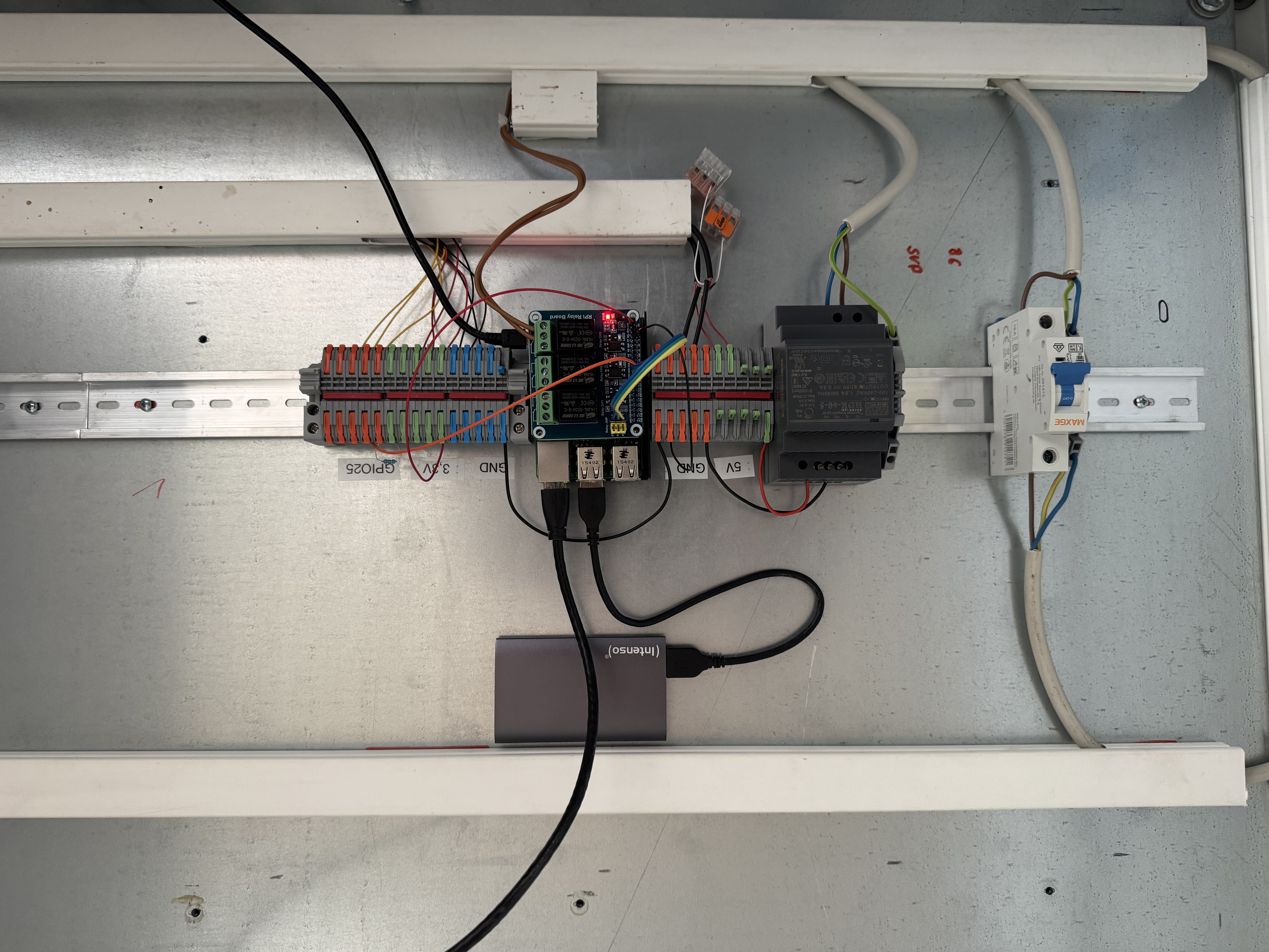 Version 1: The first compact build with Pi 4 and Automation HAT.
In Node-RED, we primarily used two packages:
node-red-contrib-1wirefor temperature reading.node-red-contrib-automation-hatfor I/O control.
The IDs of the OneWire thermometers were easily identified via the console (ls /sys/bus/w1/devices/) and assigned in Node-RED. One afternoon later, it was done: the pool was heated as soon as the panels were hot enough, and the pump turned off automatically in the evening.
Chapter 2: The Expansion
Of course, we weren’t finished yet. The system didn’t push notifications to phones, and Tom still had to backwash the filter manually—like a caveman. That had to change.
New Requirements: We needed electric valves for backwashing (inverting the flow to drain dirt). We also installed flow meters in the main line and the solar circuit, as well as pressure sensors to monitor the system state.
For the valves, we installed a 24V power supply and additional relays (Waveshare Relay Board). The entire control cabinet was rewired.
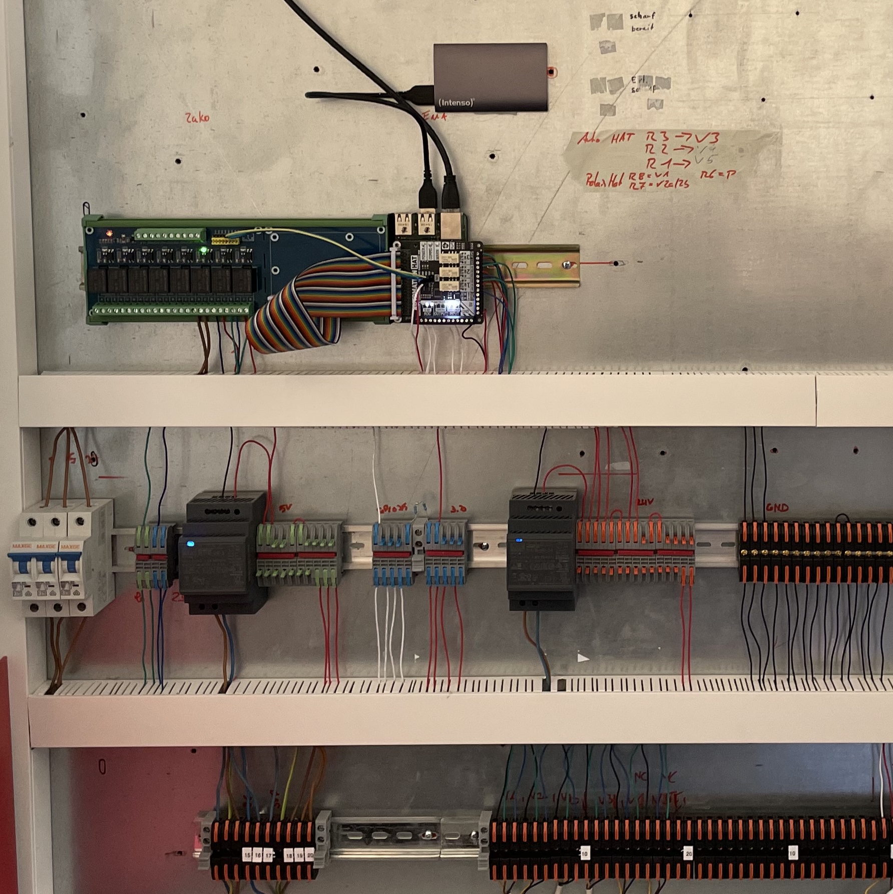 Version 2: Rewired with an additional relay board and a 24V power supply for the valves.
This created a challenge: the Automation HAT package didn’t allow for high-frequency reading of the analog inputs. However, the flow meters generated a pulse signal whose frequency we needed to capture. The solution was a separate Python script that reads the inputs at a high frequency and passes the data as JSON to Node-RED:
Script: hat_input.py (Show)
#!/usr/bin/env python3
"""
Monitors digital pulse frequencies and analog voltages on a Raspberry Pi.

This script uses the pigpio library to count pulses on two specified GPIO pins
and the Adafruit CircuitPython ADS1x15 library to read analog voltages from
three channels of an ADS1015 ADC.

The data is output as a JSON object to standard output at a configurable rate.
"""
import sys
import time
import json
import statistics
import pigpio
import board, busio
import adafruit_ads1x15.ads1015 as ADS
from adafruit_ads1x15.analog_in import AnalogIn

# --- Configuration ---
output_rate_hz = 1.0
if len(sys.argv) > 1:
    try:
        output_rate_hz = float(sys.argv[1])
        if output_rate_hz <= 0:
            sys.exit(1)
    except ValueError:
        sys.exit(1)

integration_time = 1.0 / output_rate_hz
VOLTAGE_COMPENSATION_FACTOR = 5.7

# GPIO pins for the flow sensors (using BCM numbering).
FLOW_SENSOR_PIN_1 = 26
FLOW_SENSOR_PIN_2 = 20

# --- Setup pigpio for pulse counting ---
pi = pigpio.pi()
if not pi.connected:
    sys.exit(1)

pulse_count_1 = 0
pulse_count_2 = 0

def cb1(gpio, level, tick):
    global pulse_count_1
    if level == 1: pulse_count_1 += 1

def cb2(gpio, level, tick):
    global pulse_count_2
    if level == 1: pulse_count_2 += 1

cb1_handle = pi.callback(FLOW_SENSOR_PIN_1, pigpio.RISING_EDGE, cb1)
cb2_handle = pi.callback(FLOW_SENSOR_PIN_2, pigpio.RISING_EDGE, cb2)

pi.set_glitch_filter(FLOW_SENSOR_PIN_1, 100)
pi.set_glitch_filter(FLOW_SENSOR_PIN_2, 100)

# --- Setup I2C ADC ---
i2c = busio.I2C(board.SCL, board.SDA)
ads = ADS.ADS1015(i2c)
ads.gain = 1
ads.data_rate = 128

chan0 = AnalogIn(ads, ADS.P0)
chan1 = AnalogIn(ads, ADS.P1)
chan2 = AnalogIn(ads, ADS.P2)

def get_stable_voltage(channel, num_samples=21):
    readings = []
    for _ in range(num_samples):
        readings.append(channel.voltage)
        time.sleep(0.005)
    return statistics.median(readings)

try:
    last_time = time.monotonic()
    last_pulse_count_1 = 0
    last_pulse_count_2 = 0
    next_output_time = time.monotonic()

    while True:
        next_output_time += integration_time
        sleep_time = next_output_time - time.monotonic()
        if sleep_time > 0:
            time.sleep(sleep_time)

        current_time = time.monotonic()
        elapsed_time = current_time - last_time

        current_pulse_count_1 = pulse_count_1
        current_pulse_count_2 = pulse_count_2

        if elapsed_time > 0:
            frequency_1 = (current_pulse_count_1 - last_pulse_count_1) / elapsed_time
            frequency_2 = (current_pulse_count_2 - last_pulse_count_2) / elapsed_time
        else:
            frequency_1 = frequency_2 = 0.0

        last_time, last_pulse_count_1, last_pulse_count_2 = current_time, current_pulse_count_1, current_pulse_count_2

        try:
            v1 = get_stable_voltage(chan0) * VOLTAGE_COMPENSATION_FACTOR
            v2 = get_stable_voltage(chan1) * VOLTAGE_COMPENSATION_FACTOR
            v3 = get_stable_voltage(chan2) * VOLTAGE_COMPENSATION_FACTOR
        except:
            continue

        data = {
             "pin26": round(frequency_1, 2),
             "pin20": round(frequency_2, 2),
             "analog1": round(v1, 2),
             "analog2": round(v2, 2),
             "analog3": round(v3, 2)
        }
        print(json.dumps(data))
        sys.stdout.flush()

except KeyboardInterrupt:
    pass
finally:
    cb1_handle.cancel()
    cb2_handle.cancel()
    pi.stop()
By now, the system was actually perfect: Tom could adjust the logic himself, the system could heat and backwash, and we had all critical values in view. The first winter passed, and in spring, the system passed its first functional test with flying colors.
Chapter 3: The Pitfalls of Mechanics
What happens, however, if all sensors work and the automation triggers the pump correctly, but the mechanical valves do not switch reliably?
Exactly: the pipe explodes.